It's been a very long time since I used QBasic for exploring graphics. But this week I need to learn how to do just that for a drafting assignment I had at work. I need to modify a semiconductor circuit layout for a new connector, and that required re-routing over 320 bus lines in the drawing. I wasn't going to do that manually, so I needed to learn the scripting language for this software. So that's when I turned to QBasic, both modern and old, to develop my very own "fanout" algorithm.
That drafting software is called DW-2000 and it's completely new to me. I was just learning how it's scripting language, GPE, can be used to draw when I was given this assignment. I didn't think I was comfortable enough with the language to work out the fanout algorithm in it. I usually work out ideas in Perl or LabView, or even Excel if I'm just looking at data. But for graphical stuff? The first language that came to my mind was also the very first one I learned about as a little kid, QBasic.
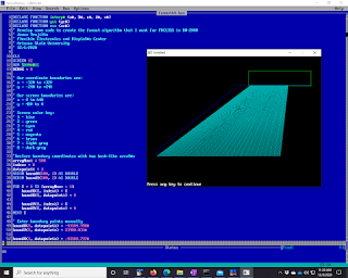
So I fired up QB64, the working man's modern QBasic, and got to work drawing polygons and lines to test out how I was going to write this code in GPE. That's an early example of what I was doing in the picture. Eventually the fanout needed to be more complicated than a simple A to B connection, and I did those final tweaks in GPE after learning how to draw path-lines in it from some example code that DW-2000 provides. GPE is a very interesting language as well. It's an array language that operates in a way that totally reminds me of the J programming language. I'm really glad I've played around with J for years before coming across GPE. It really made it much easier for me to wrap my head around the syntax of it.
So without much ado I give you some QBasic code, which works on modern QB64 and old school QBasic 4.5.
DECLARE FUNCTION interp# (a#, B#, c#, d#, x#)
DECLARE FUNCTION ys% (yc#)
DECLARE FUNCTION xs% (xc#)
' Develop some code to create the fanout algorithm that I want for FDC13SS in DW-2000
' Jovan Trujillo
' Flexible Electronics and DisplaY#s Center
' Arizona State University
' 12/1/2020

CLS
SCREEN 12
REM $DYNAMIC
DEBUG = 0

' Our coordinate boundaries are:
' x = -320 to +320
' y = -240 to +240
'
' Our screen boundaries are:
' x = 0 to 640
' y = 480 to 0
'
' Screen color key:
' 1 - blue
' 2 - green
' 3 - cyan
' 4 - red
' 5 - magenta
' 6 - brown
' 7 - light gray
' 8 - dark gray

'Declare boundary coordinates with two hash-like arraY#s
arrayMax% = 500
index% = 0
datapoint% = 1
REDIM boundX(500, 2) AS DOUBLE
REDIM boundY(500, 2) AS DOUBLE

FOR I = 0 TO (arrayMax% - 1)
    boundX(I, index%) = I
    boundX(I, datapoint%) = 0

    boundY(I, index%) = I
    boundY(I, datapoint%) = 0
NEXT I

' Enter boundary points manually
boundX(0, datapoint%) = -43104.998#
boundY(0, datapoint%) = 23900.031#

boundX(1, datapoint%) = -43104.737#
boundY(1, datapoint%) = 25096.649#

boundX(2, datapoint%) = -1980.657#
boundY(2, datapoint%) = 36489.974#

boundX(3, datapoint%) = 34770.5#
boundY(3, datapoint%) = 36489.974#

' Let's rescale these points to our screen resolution
boundPointCount% = 4

minYLayout# = boundY(0, datapoint%)
maxYLayout# = boundY(0, datapoint%)
minXLayout# = boundX(0, datapoint%)
maxXLayout# = boundX(0, datapoint%)

minXScreen# = 0!
maxXScreen# = 639!
minYScreen# = 479!
maxYScreen# = 0!

minXCart# = -320!
maxXCart# = 320!
minYCart# = -240!
maxYCart# = 240!

FOR I = 0 TO (boundPointCount% - 1)
    IF boundX(I, datapoint%) < minXLayout# THEN
        minXLayout# = boundX(I, datapoint%)
    END IF

    IF boundX(I, datapoint%) > maxXLayout# THEN
        maxXLayout# = boundX(I, datapoint%)
    END IF

    IF boundY(I, datapoint%) < minYLayout# THEN
        minYLayout# = boundY(I, datapoint%)
    END IF

    IF boundY(I, datapoint%) > maxYLayout# THEN
        maxYLayout# = boundY(I, datapoint%)
    END IF
NEXT I

minXLayout# = minXLayout# - 5000
minYLayout# = minYLayout# - 5000
maxXLayout# = maxXLayout# + 5000
maxYLayout# = maxYLayout# + 5000

IF DEBUG = 1 THEN
    PRINT "minXLayout: ", minXLayout#
    PRINT "minYLayout: ", minYLayout#
    PRINT "maxXLayout: ", maxXLayout#
    PRINT "maxYLayout: ", maxYLayout#
END IF


' Use interp to do the scaling, let's draw the boundary!
aX# = minXLayout#
bX# = minXCart#
cX# = maxXLayout#
dX# = maxXCart#

aY# = minYLayout#
bY# = minYCart#
cY# = maxYLayout#
dY# = maxYCart#

sX1 = 0#
sY1 = 0#
sX2 = 0#
sY2 = 0#

FOR I = 0 TO (boundPointCount% - 2)
    sX1# = interp#(aX#, bX#, cX#, dX#, boundX(I, datapoint%))
    sY1# = interp#(aY#, bY#, cY#, dY#, boundY(I, datapoint%))

    sX2# = interp#(aX#, bX#, cX#, dX#, boundX(I + 1, datapoint%))
    sY2# = interp#(aY#, bY#, cY#, dY#, boundY(I + 1, datapoint%))

    IF DEBUG = 1 THEN
        PRINT "I:"; I; " (LX1, LY1) = "; boundX(I, datapoint%); ","; boundY(I, datapoint%)
        PRINT "I: "; I; " (sX1, sY1) = "; xs%(sX1#); ","; ys%(sY1#)
        PRINT "I: "; I + 1; " (LX2, LY2) = "; boundX(I + 1, datapoint%); ","; boundY(I + 1, datapoint%)
        PRINT "I: "; I + 1; " (sX2, sY2) = "; xs%(sX2#); ","; ys%(sY2#)
        PRINT ""
    END IF

    LINE (xs%(sX1#), ys%(sY1#))-(xs%(sX2#), ys%(sY2#)), 1
NEXT I

IF DEBUG = 1 THEN
    ' Test what's going on with interp
    I = 0
    sX1# = interp#(aX#, bX#, cX#, dX#, boundX(I, datapoint%))
    sY1# = interp#(aY#, bY#, cY#, dY#, boundY(I, datapoint%))
    PRINT "(I, LX1, LY1) = "; I; boundX(I, datapoint%); boundY(I, datapoint%)
    PRINT "(I, sX1, sY1) = "; I; sX1#; sY1#
END IF

' Time to draw the tab locations
sX1# = interp#(aX#, bX#, cX#, dX#, 3160.499#)
sY1# = interp#(aY#, bY#, cY#, dY#, 36407.03#)
sX2# = interp#(aX#, bX#, cX#, dX#, 34793.5#)
sY2# = interp#(aY#, bY#, cY#, dY#, 38981.031#)

IF DEBUG = 1 THEN
    PRINT "(LX1#, LY1#, LX2#, LY2#): "; 3160.499#; 36407.03#; 34793.5#; 38981.031#
    PRINT "(sX1#, sY1#, sX2#, sY2#): "; sX1#; sY1#; sX2#; sY2#
    PRINT "(sX1%, sY1%, sX2%, sY2%): "; xs%(sX1#); ys%(sY1#); xs%(sX2#); ys%(sY2#)
END IF

' Draw source tab outline here.
LINE (xs%(sX1#), ys%(sY1#))-(xs%(sX2#), ys%(sY2#)), 2, B

' Draw array tab line here.
sX1# = interp#(aX#, bX#, cX#, dX#, -42993.999#)
sY1# = interp#(aY#, bY#, cY#, dY#, 24190#)
sX2# = interp#(aX#, bX#, cX#, dX#, 39946#)
sY2# = sY1#

LINE (xs%(sX1#), ys%(sY1#))-(xs%(sX2#), ys%(sY2#)), 2


' Now the real work begins! Time to try to draw a fanout!
' Array pitch is 260 um
' Source Tab pitch is 80 um
' Let's say there are 240 lines.
lineCount% = 240
arrayPitch% = 260
sourcePitch% = 80

arrayX1# = -42993.999#
arrayY1# = 24190#
tabX1# = 3970.5#
tabY1# = 36407.031#

FOR I = 1 TO lineCount%
    ' Draw lines from array to source tab
    X1% = xs%(interp#(aX#, bX#, cX#, dX#, arrayX1#))
    Y1% = ys%(interp#(aY#, bY#, cY#, dY#, arrayY1#))
    X2% = xs%(interp#(aX#, bX#, cX#, dX#, tabX1#))
    Y2% = ys%(interp#(aY#, bY#, cY#, dY#, tabY1#))
    LINE (X1%, Y1%)-(X2%, Y2%), 3
    arrayX1# = arrayX1# + arrayPitch%
    tabX1# = tabX1# + sourcePitch%
NEXT I


END

FUNCTION interp# (a#, B#, c#, d#, x#)
    ' Interpolate and return y given x and endpoints of a line
    IF (a# - c#) <> 0 THEN
        slope# = (B# - d#) / (a# - c#)
        intercept# = d# - ((B# - d#) / (a# - c#)) * c#
        interp# = slope# * x# + intercept#
    ELSE
        PRINT "interp cannot divide by zero!"
        interp# = 0#
    END IF

END FUNCTION

FUNCTION xs% (xc#)
    ' Remember that for SCREEN 12 X limites are -320 to 320
    ' Convert Cartesian coordinate system to screen coordinates
    'xs = xc + 320

    IF (xc# > 320) THEN
        xs% = 320
    ELSEIF (xc# < -320) THEN
        xs% = -320
    ELSE
        xs% = INT(xc# + 320)
    END IF
END FUNCTION

FUNCTION ys% (yc#)
    ' Remember that for SCREEN 12 Y limits are -240 to 240
    ' Convert Cartesion coordinate system to screen coordinates
    'ys = 240 - yc

    IF (yc# > 240) THEN
        ys% = 240
    ELSEIF (yc# < -240) THEN
        ys% = -240
    ELSE
        ys% = INT(240 - yc#)
    END IF

END FUNCTION
And here is the final production code for drafting out the bus lines in GPE.
      \\ fanout.gpe
\\ Hardcoded fanout macro to help us finish FDC13SS design layout
\\ Jovan Trujillo
\\ FEDC - Arizona State University
\\ 12/3/2020

menu
	"fanout2_parta"
	"fanout2_partb"
endmenu

dyadic function y := endpoints INTERP x
	local slope; intercept; a; b; c; d
	a := endpoints[1]
	b := endpoints[2]
	c := endpoints[3]
	d := endpoints[4]
	slope := (b -d)/(a-c)
	intercept := d - slope * c
	y := slope * x + intercept
endsub

niladic procedure fanout2_parta
	local lineCount; arrayPitch1; tabPitch1; arrayX1; arrayY1; tabX1; tabY1; startPoint1; endPoint1; i; endpoints
	local arrayPitch2; tabPitch2; arrayX2; tabX2; arrayY2; tabY2; startPoint2; endPoint2

\\ We do the last 62 lines in fanout_partb, and then connect these lines to the actual tab using fanout_partc and fanout_partd
	lineCount := 258
	arrayPitch1 := 260.0
	tabPitch1 := 80.0

	endpoints := (2618.325;35407.058;23308.41;28964.53)

	arrayX1 := -42994.00
	\\arrayY1 := 24190.00-8.0
	arrayY1 := 24182.00
	tabX1 := 3258.325
	tabY1 := endpoints INTERP tabX1

	arrayPitch2 := 80
	tabPitch2 := 80

	arrayX2 := 3258.325
	arrayY2 := endpoints INTERP arrayX2
	tabX2 := 3258.325
	tabY2 := 36407.058


	path       ! datatype 6
	layer 14   ! width 20
	pathtype 0 ! straight
	vlayer 14   ! solid

	startPoint1 := arrayX1, arrayY1
	endPoint1 := tabX1, tabY1
	startPoint2 := arrayX2, arrayY2
	endPoint2 := tabX2, tabY2


	for i range (iota(1,lineCount)) do
		ce startPoint1
		ce endPoint1
		ce startPoint2
		ce endPoint2
		put
		arrayX1 := arrayX1 + arrayPitch1
		tabX1 := tabX1 + tabPitch1
		startPoint1 := arrayX1, arrayY1
		tabY1 := endpoints INTERP tabX1
		endPoint1 := tabX1, tabY1
		tabX2 := tabX2 + tabPitch2
		arrayX2 := arrayX2 + arrayPitch2
		arrayY2 := endpoints INTERP arrayX2
		startPoint2 := arrayX2, arrayY2
		endPoint2 := tabX2, tabY2

	enddo

	view

endsub

niladic procedure fanout2_partb
local lineCount; arrayPitch1; tabPitch1; arrayX1; arrayY1; tabX1; tabY1; startPoint1; endPoint1; i; endpoints
local arrayPitch2; tabPitch2; arrayX2; tabX2; arrayY2; tabY2; startPoint2; endPoint2

	lineCount := 62
	arrayPitch1 := 260
	tabPitch1 := 80.0

	endpoints := (23258.296; 29005.016; 23308.41; 29033.135)

	arrayX1 := 24086.00
	\\arrayY1 := 24190.00 - 8.0
	arrayY1 := 24182.00
	tabX1 := 23898.296
	tabY1 := endpoints INTERP tabX1

	arrayPitch2 := 80
	tabPitch2 := 80

	arrayX2 := 23898.296
	arrayY2 := endpoints INTERP arrayX2
	tabX2 := 23898.325
	tabY2 := 36407.058

	startPoint2 := arrayX2, arrayY2
	endPoint2 := tabX2, tabY2


	path       ! datatype 6
	layer 14   ! width 20
	pathtype 0 ! straight
	vlayer 14   ! solid

	startPoint1 := arrayX1, arrayY1
	endPoint1 := tabX1, tabY1

	for i range (iota(1,lineCount)) do
		ce startPoint1
		ce endPoint1
		ce startPoint2
		ce endPoint2
		put
		arrayX1 := arrayX1 + arrayPitch1
		tabX1 := tabX1 + tabPitch1
		startPoint1 := arrayX1, arrayY1
		tabY1 := endpoints INTERP tabX1
		endPoint1 := tabX1, tabY1
		tabX2 := tabX2 + tabPitch2
		arrayX2 := arrayX2 + arrayPitch2
		arrayY2 := endpoints INTERP arrayX2
		startPoint2 := arrayX2, arrayY2
		endPoint2 := tabX2, tabY2
	enddo
	view
endsub
Fun stuff. In the future I want to add boundary checking code and some adaptive approach to drawing all those paths so I don't have to think about the geometry. Just give it A and B and the pitch and number of lines and let the code draw the pathways. I'll be using QBasic to help me work all that out as well!
